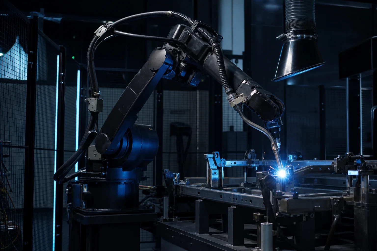
A practical engineering guide for manufacturers planning robotic welding fixtures, covering part location, clamping, weld access, distortion control, safety, cycle time and quotation data.
Why Fixture Design Matters More Than Many Buyers Expect
In robotic welding automation, the fixture is not a simple holding frame. It is the foundation that controls part location, weld access, repeatability, operator loading, distortion management and cell productivity. A strong robot and welding power source cannot compensate for parts that move, vary or sit in a different position every cycle. For this reason, robotic welding projects should begin with fixture strategy before final robot model selection. Kynex Robots evaluates the part, welding process, robot options, positioner needs and operator workflow as one integrated system.
Start With Part Location and Datum Strategy
A welding fixture should locate the part from stable and repeatable datums. The fixture designer needs to understand which surfaces, holes, edges or reference points can reliably position the part. If the part is manually fabricated with large variation, the fixture may need adjustable locators, guided loading or pre-positioning checks. Datum strategy also affects inspection. When the same reference points are used for loading, welding and quality control, the entire process becomes easier to stabilize. Factories should prepare drawings, tolerance information and photos of current manual welding setups before requesting a robotic welding proposal.
Clamping Must Control Movement Without Blocking Welds
Clamps must hold the part firmly enough to resist movement, welding heat and operator handling, but they must not block the torch path or create collision risk. Manual clamps may be suitable for lower-volume cells. Pneumatic clamps can improve consistency and reduce loading time, but they add valves, sensors, safety logic and maintenance requirements. The best clamping method depends on material thickness, part shape, weld sequence, access space and cycle time. Clamp location should be reviewed with the robot torch angle, nozzle, cable package and possible spatter accumulation in mind.
Weld Access Should Be Simulated Before Manufacturing the Fixture
A fixture that looks practical on a workbench may fail when the robot torch, cable package and safety envelope are considered. Robotic welding needs room for approach angle, travel angle, torch stick-out, cable movement and collision avoidance. Tight corners, deep boxes, internal welds and overlapping brackets can be difficult to reach. If a positioner is used, the fixture must also support rotation without cable interference or part movement. Early access review reduces expensive rework after the fixture has already been built.
Distortion Control Is Part of Fixture Engineering
Welding heat can pull, twist or shrink metal parts. Fixtures help manage distortion by controlling location, clamping sequence and weld sequence, but excessive restraint can also create stress or make unloading difficult. A robotic welding cell should consider tack welds, weld length, heat input, sequence, cooling, gap control and part release strategy. For thin materials, distortion control may require shorter weld segments, staggered sequence or improved part fit-up. For heavier structures, fixture stiffness and positioner capacity become more important. Distortion should be treated as a process issue, not only a mechanical fixture issue.
Loading Workflow Affects Real Cycle Time
The official robot welding time is only part of the production cycle. Operators still need to load parts, position components, close clamps, check fit-up, unload finished parts and manage inspection or rework. A fixture that is difficult to load may reduce the value of automation. Dual-station fixtures, rotary positioners or sliding tables can allow one side to be loaded while the robot welds the other side. However, these layouts add cost and require more safety planning. The right choice depends on target output, part weight, operator ergonomics and available floor space.
Sensors and Error Proofing Improve Production Stability
Robotic welding fixtures can include sensors to confirm part presence, clamp position, fixture rotation, door status or cylinder position. These signals help the PLC and robot prevent welding when parts are missing or incorrectly loaded. Error proofing is especially useful when product families have similar components, multiple brackets or left/right-hand versions. Sensors add cost, wiring and maintenance requirements, so they should be used where the failure risk is meaningful. A practical design focuses on preventing expensive or common mistakes rather than adding unnecessary complexity.
Positioners Expand Weld Access but Change the Fixture Requirements
A welding positioner can rotate or tilt the part to improve torch access, weld quality and cycle time. It can help maintain better welding orientation and reduce difficult overhead or vertical welding paths. However, adding a positioner changes fixture design. The fixture must be balanced, rigid, safe during rotation and compatible with cable routing. The positioner payload must include the part, fixture, clamps and any tooling. Buyers should not evaluate the robot payload alone. The entire moving mass and center of gravity need to be reviewed before final equipment selection.
Fixture Maintainability Should Be Designed From the Start
Production fixtures experience spatter, heat, operator contact, clamp wear, cable movement and repeated loading. Wear surfaces, copper backup bars, replaceable locators, clamp guards and cleaning access can reduce downtime. If a fixture requires long maintenance time or special disassembly for simple cleaning, production availability will suffer. Good fixture design includes maintainable details: accessible fasteners, replaceable pins, documented locator settings, clear part loading marks and practical spare parts planning. Maintainability is a major part of long-term welding automation success.
Safety Is Connected to Fixture and Operator Workflow
Fixture design affects how operators reach into the cell, where hands are placed, how clamps close and how the part is unloaded. Pneumatic clamps may require two-hand controls, safe clamp logic or guarded areas depending on the application. Heavy parts may require lifting aids. Sharp edges, hot parts and spatter must be considered. The safety system should be designed together with fixture loading, robot movement, positioner rotation and maintenance access. A welding cell that is safe but slow to reset can lose productivity, while a fast but unsafe cell is not acceptable.
Common Fixture Design Mistakes
Common mistakes include designing the fixture after the robot has already been selected, blocking torch access with clamps, ignoring cable package movement, underestimating part variation, using weak locators, making the fixture difficult to clean, failing to plan distortion control and focusing only on robot welding time instead of total operator cycle time. Another frequent issue is building one fixture for too many product variants without defining which dimensions can actually be shared. Flexible fixture design can be valuable, but uncontrolled flexibility creates unstable welding results.
Quotation Data Needed for Robotic Welding Fixtures
Manufacturers can speed up engineering review by preparing part drawings, 3D models when available, photos, videos of current manual welding, material type, thickness, tolerance requirements, weld length, joint type, annual volume, hourly output target, current fixture photos, loading method, inspection standard and available floor space. If the project includes several similar parts, representative families should be grouped by size, weld type and fixture concept. A clear data package helps the integrator judge whether a fixed fixture, adjustable fixture, positioner fixture or phased automation approach is most practical.
How Kynex Robots Supports Welding Fixture Integration
Kynex Robots works as a robotic system integrator for welding automation projects. Fixture design is considered together with robot option evaluation, welding power source selection, torch access, positioner needs, PLC/HMI control, safety guarding, installation and commissioning. Kynex Robots does not present itself as a robot manufacturer. The value is in engineering a complete robotic welding cell that fits the manufacturer production process and project requirements.
FAQ: Can Existing Manual Welding Fixtures Be Reused?
Existing manual fixtures can sometimes be reused or modified, but they must be checked for repeatability, torch access, clamping stability, safety and compatibility with robot motion. Many manual fixtures are designed for human flexibility rather than robotic repeatability, so modification is often needed.
FAQ: Is a Positioner Always Required?
No. Some parts can be welded with a fixed table or simple two-station layout. A positioner becomes more valuable when weld access, welding orientation, cycle time or part size makes fixed fixturing inefficient. The decision should be based on the part and process, not only on equipment preference.
FAQ: What Makes a Fixture Ready for Robotic Welding?
A robotic welding fixture should locate parts repeatably, clamp them securely, leave access for torch movement, support safe loading, manage distortion and communicate critical status signals when needed. It should also be maintainable in daily production.
Robotic Welding Fixture Engineering Checklist
| Fixture Area | Engineering Purpose | Buyer Data to Prepare |
|---|---|---|
| Datum and part location | Controls repeatability and weld path stability | Drawings, tolerance points, current fixture photos |
| Clamping strategy | Prevents movement while keeping welds accessible | Material thickness, part variation, manual loading method |
| Torch access | Confirms robot can reach each weld safely | Weld map, joint type, photos or 3D model |
| Distortion control | Reduces deformation and rework risk | Weld length, sequence, material, current defects |
| Positioner compatibility | Improves access and orientation when needed | Part weight, fixture weight estimate, center of gravity notes |
| Sensors and PLC signals | Prevents missing-part or unclamped welding errors | Critical checks, clamp status needs, safety requirements |
| Operator workflow | Improves loading speed and daily usability | Target output, loading time, part weight, available space |