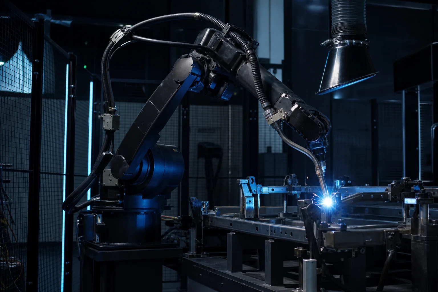
A practical robotic welding cell layout guide for manufacturers, covering robot reach, fixtures, positioners, operator loading, weld access, safety, controls and quotation data.
Why Welding Cell Layout Decides Real Production Performance
A robotic welding cell is not only a robot arm placed beside a table. The layout decides how parts are loaded, how the fixture holds the workpiece, how the robot reaches each weld, how the operator stays safe, how fumes are removed and how the cell recovers after a fault. A strong welding robot can still underperform if the cell layout blocks torch access, slows loading or creates difficult maintenance conditions. Kynex Robots evaluates robotic welding projects as complete integration systems, combining selected robot options with fixtures, welding equipment, positioners, PLC/HMI control and safety architecture.
Start With Part Size, Weld Map and Product Family
The first layout question is what the robot must weld. Buyers should prepare drawings, photos, part dimensions, material thickness, weld length, joint type, current manual welding videos and product variation. A small bracket cell, a sheet metal frame cell and a heavy structural component cell require different layouts. The weld map should show where each weld is located, which side must be accessed and whether the torch needs special angles. Product families should be grouped by size and fixture concept so the cell can support real production without becoming too complex.
Choose Between Fixed Table, Dual Station or Positioner Layout
A fixed table can be practical for simple parts, low-volume production or early automation phases. A dual-station layout allows an operator to load one fixture while the robot welds another, improving utilization when loading time is significant. A positioner can rotate or tilt the workpiece to improve weld access, welding orientation and cycle time. The right layout depends on part weight, weld length, target output, operator workflow, available floor space and budget. A positioner is useful when it solves access or productivity problems, but it should not be added just because it looks more advanced.
Robot Reach Must Be Checked With Tooling and Torch Angle
Robot catalog reach is not enough for cell layout. The real reach must include torch length, cable package, fixture height, clamps, part geometry, safety distance and approach angle. Some welds require the torch to approach from a specific direction to maintain quality. Deep corners, inner frames and overlapping brackets can create collision risk. Offline simulation or reach review should happen before finalizing the fixture and robot mounting position. If the robot is placed poorly, the project may require unnecessary repositioning, oversized robot selection or fixture redesign.
Fixture Location Controls Repeatability and Cell Rhythm
Fixtures define how parts are located and clamped. In a robotic welding cell, fixture repeatability has direct impact on weld quality because the robot follows programmed paths. The fixture should locate stable datum points, control part movement, allow torch access, reduce distortion and support fast loading. Fixture height and orientation also affect operator ergonomics and robot motion. A fixture that is excellent mechanically but hard to load will reduce real productivity. Layout review should include part loading path, clamp operation, finished part removal and access for cleaning spatter or replacing wear parts.
Operator Loading Workflow Should Be Designed Before Guarding
Operator workflow affects cycle time and safety. The layout should define where the operator stands, how raw parts arrive, how parts are placed into the fixture, how clamps close, how finished parts leave the cell and how inspection happens. Heavy parts may need cranes, hoists or lift tables. Small components may need bins or kitting areas. If the operator walks too far or reaches awkwardly into the fixture, the cell will be slower and less safe. Safety guarding should be designed around the real workflow rather than added after the equipment positions are already fixed.
Positioners Improve Access but Add Engineering Requirements
A welding positioner can improve torch access and welding orientation, especially for frames, boxes, circular components and multi-side welds. It can reduce difficult vertical or overhead weld paths and help maintain more stable weld quality. However, the positioner changes the engineering scope. The payload must include the part, fixture, clamps and tooling. The center of gravity, rotation clearance, cable routing, fixture balance and safety zone must be reviewed. A poorly planned positioner can create collision risk or operator loading problems. The decision should be based on weld access and production value.
Safety Layout Must Balance Protection and Usability
Robotic welding safety includes fencing, interlocked doors, light curtains, area scanners, emergency stops, welding arc protection, fume extraction, hot part handling and safe reset procedures. A safe cell should also be practical to run. If every minor fault requires a long reset process, operators may lose productivity and confidence. Safety devices should protect people while allowing efficient loading, maintenance and troubleshooting. The layout must consider robot reach, positioner movement, sparks, spatter, fume direction, maintenance doors and emergency access.
Fume Extraction and Welding Environment Need Early Planning
Robotic welding creates fumes, spatter, heat, arc light and noise. Fume extraction should be considered before final layout because ducting, hoods, airflow and access space can affect the cell. Extraction must not interfere with robot motion or fixture loading. The cell should also consider cable protection, anti-spatter maintenance, welding wire access, gas supply, power source placement and service clearance. A clean and maintainable welding environment improves uptime and helps operators manage daily production.
PLC, Robot Handshake and HMI Make the Cell Operable
A welding cell needs coordination between the robot, welding power source, positioner, clamps, sensors, safety devices and operator interface. The PLC or cell controller should manage part present signals, clamp confirmation, door status, positioner readiness, fault alarms and production modes. The HMI should help operators select recipes, view alarms, run manual functions and recover safely after stops. Good control design reduces downtime because operators can understand what happened and how to restart correctly. Poor control design makes even good hardware difficult to use.
Cycle Time Should Include Robot Time and Human Time
Many projects overestimate productivity by looking only at robot welding time. Real cycle time includes loading, part positioning, clamp closing, weld sequence, robot motion, positioner movement, cooling, inspection and unloading. If loading time is longer than welding time, a dual-station layout may be necessary. If weld access requires many torch repositioning moves, a positioner may reduce robot motion time. A realistic cycle time study should compare current manual welding, target output, takt time, operator workflow and expected robot utilization.
Common Welding Cell Layout Mistakes
Common mistakes include selecting the robot before reviewing weld access, designing fixtures that block the torch, underestimating operator loading time, placing the welding power source where maintenance is difficult, ignoring fume extraction, leaving too little space for doors or service access, and adding a positioner without checking payload and center of gravity. Another common mistake is trying to automate too many product variants in one cell without defining the fixture strategy. Flexibility is useful, but uncontrolled variation creates programming, clamping and quality problems.
Quotation Data Needed for a Welding Cell Layout Proposal
Useful proposal data includes part drawings, photos, videos, material, thickness, weld length, joint type, annual volume, hourly target output, current welding method, fixture photos, quality standard, inspection requirements, available floor space, loading method, preferred robot options, budget range and expected schedule. If multiple products will share the cell, they should be grouped by size, weld type, fixture method and production frequency. Better data allows the integrator to recommend a practical fixed-table, dual-station or positioner-based layout.
How Kynex Robots Supports Welding Cell Layout Projects
Kynex Robots works as a robotic system integrator for welding automation projects. The work can include cell layout planning, robot option evaluation, fixture strategy, welding equipment coordination, positioner evaluation, PLC/HMI control, safety design, installation, commissioning and after-sales support. Kynex Robots is not a robot manufacturer. The role is to integrate selected robot options and automation components into a working robotic welding cell based on the factory process and project requirements.
FAQ: Is a Positioner Required for Robotic Welding?
No. A positioner is not always required. It is useful when it improves weld access, welding orientation, quality stability or cycle time enough to justify the added cost and complexity. Some parts can be welded effectively on a fixed table or dual-station fixture.
FAQ: What Is the Best Welding Cell Layout?
There is no universal best layout. The best welding cell layout depends on part size, weld access, loading time, fixture strategy, target output, floor space, safety requirements and budget. A practical layout should be selected after reviewing the real part and production workflow.
FAQ: Can One Welding Cell Handle Many Different Products?
One cell can handle multiple products when fixture strategy, robot reach, program management and production scheduling are planned carefully. However, too much variation can reduce repeatability and make automation inefficient. Product families should be grouped before final layout design.
Robotic Welding Cell Layout Planning Matrix
| Layout Area | Engineering Decision | Buyer Data to Prepare |
|---|---|---|
| Part and weld map | Defines robot reach, fixture orientation and torch access | Drawings, photos, weld length, joint type, material thickness |
| Fixture strategy | Controls repeatability and loading workflow | Current fixture photos, datum points, clamping needs, product variation |
| Positioner decision | Improves access and orientation when justified | Part weight, fixture weight, center of gravity, target output |
| Operator workflow | Determines real cycle time and ergonomic layout | Loading method, part arrival, unloading method, inspection steps |
| Safety architecture | Protects operators while supporting daily recovery | Operator stations, doors, light curtains, emergency stop needs |
| Fume extraction and utilities | Supports welding environment and maintenance | Welding process, gas supply, power source location, ducting limits |
| PLC/HMI controls | Coordinates robot, clamps, positioner and alarms | Sensor needs, recipe requirements, fault recovery workflow |